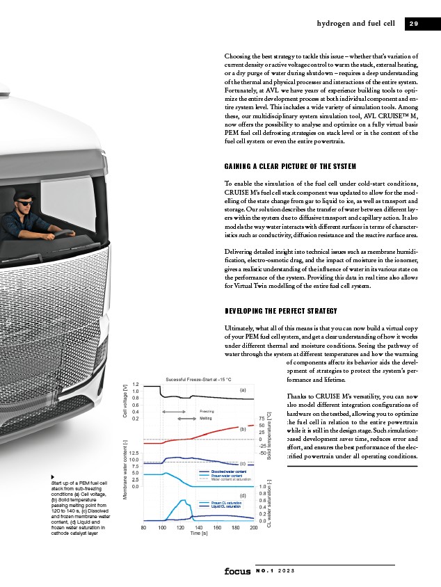
Start up of a PEM fuel cell
stack from sub-freezing
conditions (a) Cell voltage,
(b) Solid temperature
passing melting point from
120 to 140 s, (c) Dissolved
and frozen membrane water
content, (d) Liquid and
frozen water saturation in
cathode catalyst layer
hydrogen and fuel cell 2 9
Choosing the best strategy to tackle this issue – whether that’s variation of
current density or active voltage control to warm the stack, external heating,
or a dry purge of water during shutdown – requires a deep understanding
of the thermal and physical processes and interactions of the entire system.
Fortunately, at AVL we have years of experience building tools to optimize
the entire development process at both individual component and entire
system level. This includes a wide variety of simulation tools. Among
these, our multidisciplinary system simulation tool, AVL CRUISE™ M,
now offers the possibility to analyse and optimize on a fully virtual basis
PEM fuel cell defrosting strategies on stack level or in the context of the
fuel cell system or even the entire powertrain.
GAINING A CLEAR PICTURE OF THE SYSTEM
To enable the simulation of the fuel cell under cold-start conditions,
CRUISE M’s fuel cell stack component was updated to allow for the modelling
of the state change from gas to liquid to ice, as well as transport and
storage. Our solution describes the transfer of water between different layers
within the system due to diffusive transport and capillary action. It also
models the way water interacts with different surfaces in terms of characteristics
such as conductivity, diffusion resistance and the reactive surface area.
Delivering detailed insight into technical issues such as membrane humidification,
electro-osmotic drag, and the impact of moisture in the ionomer,
gives a realistic understanding of the influence of water in its various state on
the performance of the system. Providing this data in real time also allows
for Virtual Twin modelling of the entire fuel cell system.
DEVELOPING THE PERFECT STRATEGY
Ultimately, what all of this means is that you can now build a virtual copy
of your PEM fuel cell system, and get a clear understanding of how it works
under different thermal and moisture conditions. Seeing the pathway of
water through the system at different temperatures and how the warming
of components affects its behavior aids the development
N O . 1 2 0 2 3
of strategies to protect the system’s performance
and lifetime.
Thanks to CRUISE M’s versatility, you can now
also model different integration configurations of
hardware on the testbed, allowing you to optimize
the fuel cell in relation to the entire powertrain
while it is still in the design stage. Such simulationbased
development saves time, reduces error and
effort, and ensures the best performance of the electrified
powertrain under all operating conditions.
Dissolved water content
Frozen water content
Water content at saturation
Frozen CL saturation
Liquid CL saturation