>
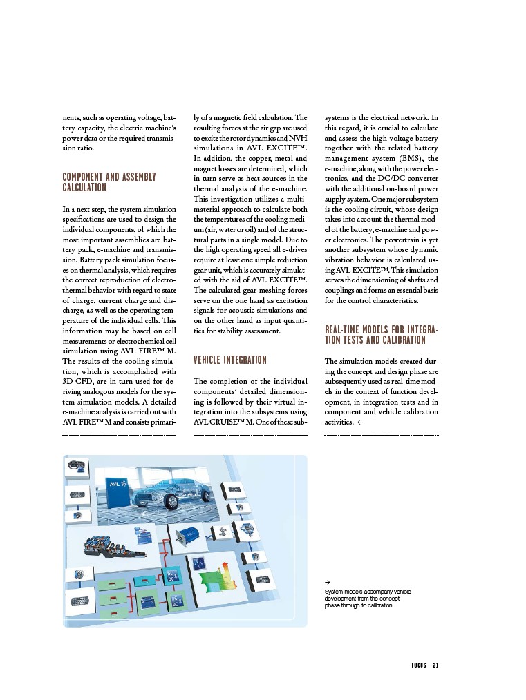
System models accompany vehicle
development from the concept
phase through to calibration.
F O C U S 2 1
nents, such as operating voltage, battery
capacity, the electric machine’s
power data or the required transmission
ratio.
COMPONENT AND ASSEMBLY
CALCULATION
In a next step, the system simulation
specifications are used to design the
individual components, of which the
most important assemblies are battery
pack, e-machine and transmission.
Battery pack simulation focuses
on thermal analysis, which requires
the correct reproduction of electrothermal
behavior with regard to state
of charge, current charge and discharge,
as well as the operating temperature
of the individual cells. This
information may be based on cell
measurements or electrochemical cell
simulation using AVL FIRE™ M.
The results of the cooling simulation,
which is accomplished with
3D CFD, are in turn used for deriving
analogous models for the system
simulation models. A detailed
e-machine analysis is carried out with
AVL FIRE™ M and consists primarily
of a magnetic field calculation. The
resulting forces at the air gap are used
to excite the rotor dynamics and NVH
simulations in AVL EXCITE™.
In addition, the copper, metal and
magnet losses are determined, which
in turn serve as heat sources in the
thermal analysis of the e-machine.
This investigation utilizes a multimaterial
approach to calculate both
the temperatures of the cooling medium
(air, water or oil) and of the structural
parts in a single model. Due to
the high operating speed all e-drives
require at least one simple reduction
gear unit, which is accurately simulated
with the aid of AVL EXCITE™.
The calculated gear meshing forces
serve on the one hand as excitation
signals for acoustic simulations and
on the other hand as input quantities
for stability assessment.
VEHICLE INTEGRATION
The completion of the individual
components’ detailed dimensioning
is followed by their virtual integration
into the subsystems using
AVL CRUISE™ M. One of these sub-
systems is the electrical network. In
this regard, it is crucial to calculate
and assess the high-voltage battery
together with the related battery
management system (BMS), the
e-machine, along with the power electronics,
and the DC/DC converter
with the additional on-board power
supply system. One major subsystem
is the cooling circuit, whose design
takes into account the thermal model
of the battery, e-machine and power
electronics. The powertrain is yet
another subsystem whose dynamic
vibration behavior is calculated using
AVL EXCITE™. This simulation
serves the dimensioning of shafts and
couplings and forms an essential basis
for the control characteristics.
REAL-TIME MODELS FOR INTEGRATION
TESTS AND CALIBRATION
The simulation models created during
the concept and design phase are
subsequently used as real-time models
in the context of function development,
in integration tests and in
component and vehicle calibration
activities. <