The new release brings new capability enabling the specification of adaptive mesh refinement of the embedded solid surfaces directly at the start of the simulation. The benefit is that the simulation already starts with the fully refined mesh without further refinements and rezoning.
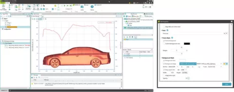
Automatic report generation has been extended to include the vehicle aerodynamics solution. It enables a fully automated report generation and saves you a lot of time when post-processing the simulation results. It can only be used in conjunction with the Vehicle Aerodynamics workflow app. The automatically generated report includes 3D results (Figure 1) in terms of pressure, velocity and TKE on the surface, contour plots at the center, and other characteristic planes and Cd/Cl diagrams, all scaled automatically according to the specific geometry and conditions.
Figure 1: Example of an automatically generated report for the assessment of aerodynamic performance
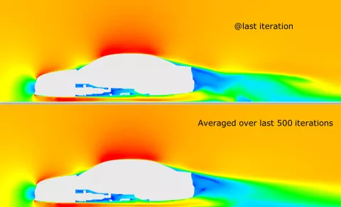
The formula for additional, averaged quantities is added to the model setup. Currently, absolute pressure, velocity, turbulent kinetic energy, turbulent dissipation rate and viscosity are averaged. The starting iteration for averaging is defined in the GUI. Note that the averaging is also available for steady RANS calculations, which is very useful in the event the solution oscillates slightly around a mean value (see Figure 2).

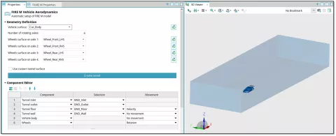
Default wind tunnels can be automatically created with the "Create tunnel" button in Geometry Definition. The button becomes active after the "Vehicle surface" has been defined, since the tunnel size is computed based on the vehicle size. You can also use your own tunnel surface, select the "Use custom tunnel surface" check box and then provide the surface mesh of the wind tunnel.

A background image can be added to line charts to put the displayed data into context. The image zooms and pans with the chart, can be shown in front of or behind the grid, and can be made semi-transparent. This visualization is very useful when analyzing aerodynamic performance data such as accumulated drag and lift coefficients, or some local quantities of interest like pressure coefficient.

The numerical treatment of the fluxes in embedded solid simulations has been improved for 2023 R1. The new default setup corresponds to the 2022 R2 setup, where, additionally, the user-defined parameter EMB_PREFOR_MIXFLUX_CORRECTION = 3 was set. The new default numerical treatment provides high accuracy and good solver performance in embedded solid simulations, especially for aerodynamic simulations.
The new installation example with the accompanying documentation is available with 2023 R1. The model can be downloaded from AVL Resource Box. After unzipping the downloaded zip-file (FIRE_M_9557_Aerodynamics_Solution_App.zip), you can access all the necessary files for this example (surface meshes of car and wind tunnel). The new example demonstrates fast and user-friendly workflow, suitable not only to experienced CFD engineers, but also for non-CFD users. The solution App based on the embedded body approach dramatically reduces pre-processing effort, yet delivering reliable results comparable to the conventional methods. It provides fully automated mesh preparation, simulation setup and report generation, being especially appealing for design exploration and optimization for car aerodynamics, without need for (re)meshing.