Don't miss the latest enhancements in the area of Virtual System Development.
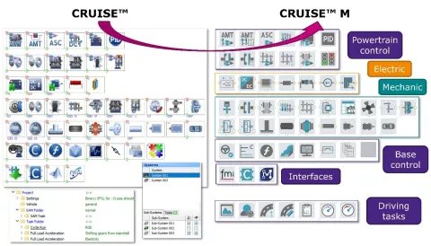
Version 2023 R1 brings AVL CRUISE™ M and AVL CRUISE™ closer together. CRUISE models can now be loaded into CRUISE M, thus automating the entire process of model migration.
Specifically, this means that identical components are mapped to new CRUISE M components. Deviating components are mapped to similar components or component groups. During the process, the entire connection topology is interpreted and a corresponding CRUISE M model network is built. Task folders and tasks from CRUISE are transferred to case sets and cases, subsystems are mapped to layers, and both are maintained in CRUISE M scenarios.
If deviations occur that cannot be resolved by the software itself, a dedicated migration protocol guides you manually through the remaining steps.
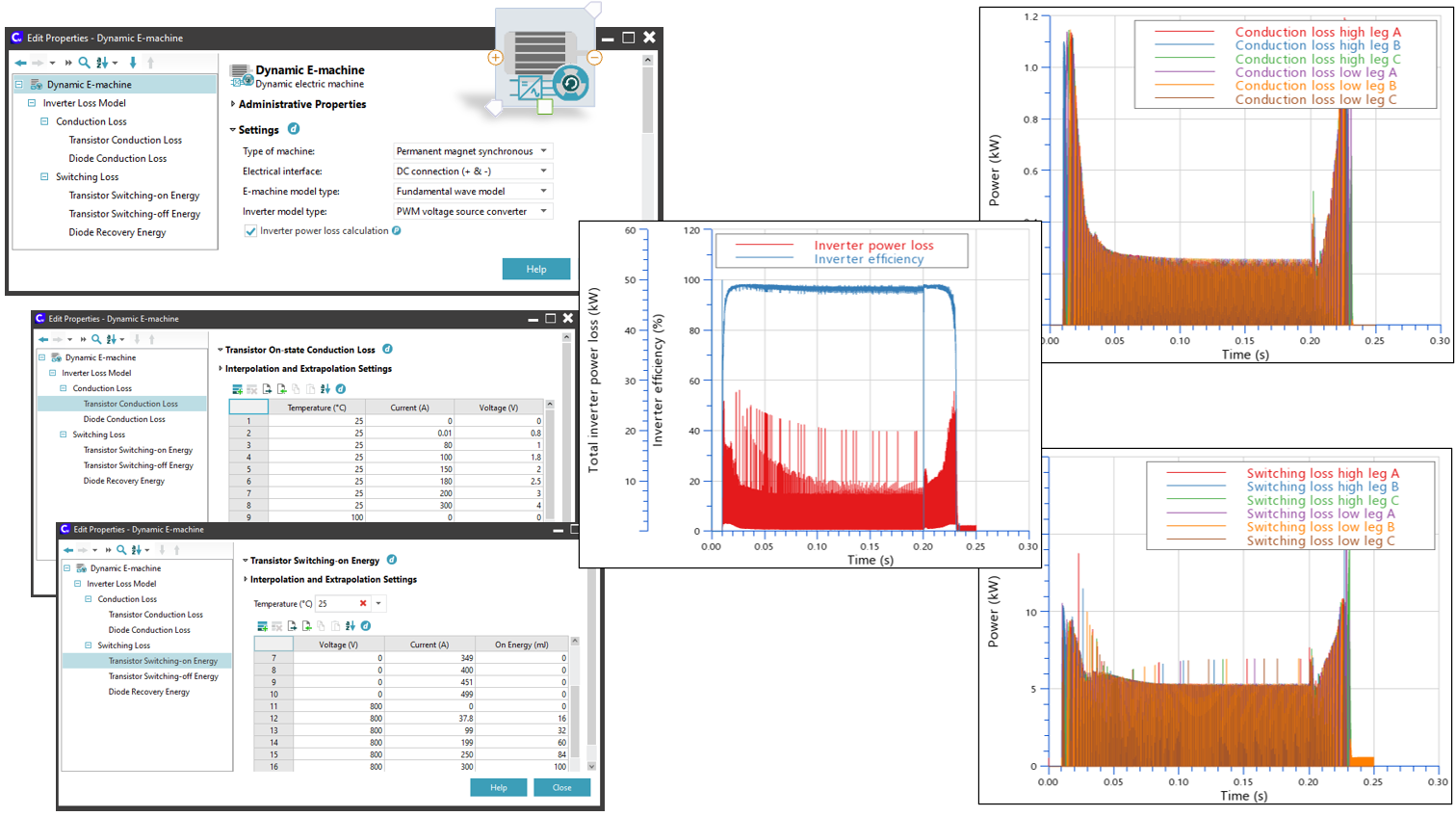
The Dynamic E-Machine component provides the option of an internal inverter that models six ideal switches responding to an externally provided PWM signal. The approach allows the e-machine to be run on three phases considering three-phase details. This version of CRUISE M enables the behavior of inverter losses to be modeled one step closer to reality.
Two inverter types are available, "IGBT with diode" and "MOSFET". CRUISE M maps the switching energies into power losses and uses them together with the conduction losses to calculate the corresponding current in the electrical network. All details on the losses are available on the data bus network and can be used for any kind of control purpose or for simple online analysis during a running simulation.
The export of CRUISE M model FMUs is taken to the next level. This version enables models to be either exported according to the classic FMI 2.0 standard or CRUISE M FMUs can be generated according to the latest FMI 3.0 standard. The exported CRUISE M FMUs using the FMI 3.0 standard offer the same functional scope as the 2.0 standard. Beyond that, non-scalars of data type characteristics (i.e. two-column tables, y(x)) can now also be exported. Whenever a physical aspect is covered by a characteristic, it can be exposed and the table can be changed from the hosting environment without needing to return to CRUISE M's GUI.

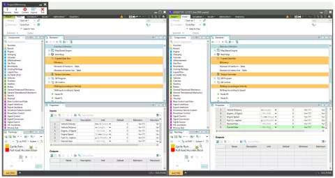
Managing the data of different model versions is key to efficiently maintaining the progress of a model. This release provides a new and more rigorous diff functionality that works on the level of an entire project, comprising all models that are packed within the project, including configurations in the Simulations, Results, Optimization and Parameters tabs.
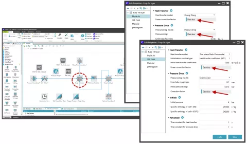
Air conditioning systems or heat pumps are essential parts of the vehicle thermal management system (VMTS) of battery electric vehicles. This version of CRUISE M increases the versatility when configuring different components of our VLE circuits. These are the MPET, Fin & Tube, Plate, Tube & Tube and Tube Heat Exchangers, as well as the VLE Pipe component. All these components offer the possibility of changing the constant inputs of heat and pressure drop correction factors to be variable via CRUISE M’s data bus network. These inputs, together with additional data bus outputs on mass flow, volume flow, etc., are the basis for performing component parameterization in a closed loop.
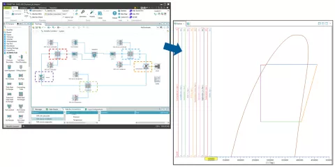
Ph-diagrams are a commonly used and very effective way of assessing the operating behavior of air conditioning or waste heat recovery systems. This version of CRUISE M provides the service of an online inspection of ph-diagrams during a running simulation. The online ph-diagram is given in a simplified format showing the saturation lines of the selected fluid and the operating lines (i.e. compression, condensation, expansion and evaporation) of all involved components.
